제품에 대한 기술자료를 한번에
제품 목차
우주항공 PT 소자
우주항공 PT 소자에 대한 상세한 기술 자료를 제공합니다.
This specification details the ratings, physical and eletrical characteristics, test and inspection data for thermistors, Platinum Resistance (Thermally sensitive resistors), based on basis type thermistors (PT element) defined in ESCC 4006/015, with ESCC-wires.
It shall be read in conjunction with ESCC Generic Specification listed under Applicable Documents para.
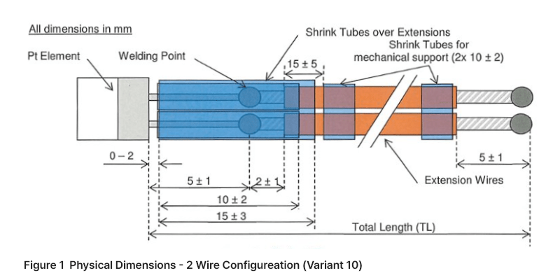
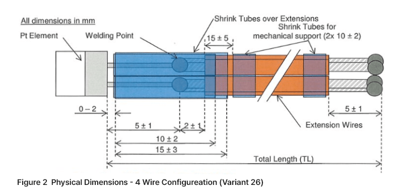
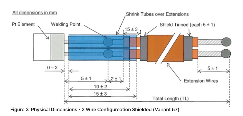
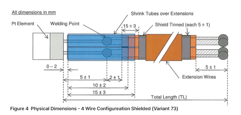
Variants of the basis type thermistors (PT element) specified herein, which are also covered by this specification, are given in AD 2. Variants for the tail extension, are given in Table 1 for the wires and in Table 2 for shrink tubes.
The maximum ratings, which shall not be exceeded at any time during use or storage, applicable to the thermistors specified herein, are as written in AD 2, AD 3 and Type Variants of the Shrink Tubes Table 2.
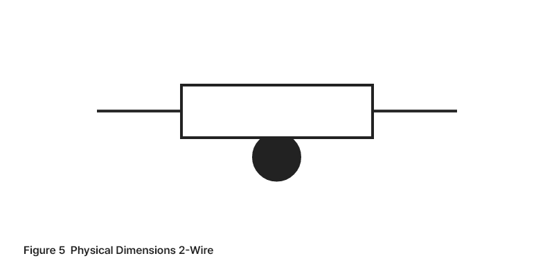
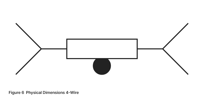
The physical dimensions of the tail extension specified herein are shown in para. 3.2 Physical Dimensions. The thiermistor is defined in AD 2
The functional diagram of the platinum temperatures sensor will tail extension specified herein is shown in Figure 5 and Figure 6
The following documents form part of this specification and shall be read in conjunction with:
- AD1 : ESCC Generic Specification No. 4006
- AD2 : ESCC Detail Specification No. 4006/015
- AD3 : ESCC Detail Specification No. 3901/019
- AD4 : ESCC Basic Specification No. 21300
For purpose of this specification, terms, definitions, abbreviations, symbols and units are specified according AD 4 and shall apply.
IST = Innovative Sensor Technology IST AG
Type variants of the PT Element R/T characteristics according AD2.
| ESCC Variant No. (AD 3) | Figure | ESA Wire; ESCC 3901 019 with CELLOFLOIN® / Polyimide tape | |||||||
|---|---|---|---|---|---|---|---|---|---|
| Conductor | Shield Strand Ømm | Overall Max Ømm | Max weight g/m | ||||||
| AWG | Stranding No x Ømm | Max Ømm | Nom. Cross section mm2 | ||||||
| 10 | Figure 1 | 28 | 7 x 0.127 SPCA | 0.47 | 0.09 | 258 | NA | 1.70 | 2.80 |
| 26 | Figure 2 | 28 | 7 x 0.127 SPCA | 0.47 | 0.09 | 260 | NA | 2.10 | 6.00 |
| 57 | Figure 3 | 28 | 7 x 0.127 SPCA | 0.47 | 0.09 | 258 | 0.079 | 2.10 | 6.10 |
| 73 | Figure 4 | 28 | 7 x 0.127 SPCA | 0.47 | 0.09 | 260 | 0.079 | 2.50 | 10.40 |
| Manufacturers Reference | Material | Shrink tubes | ||||
|---|---|---|---|---|---|---|
| Inside Diameter | Wall thickness Recovered after heating(nominal) mm | Operating Temperature range ℃ | Shrink ratio | |||
| Min. Ø as supplied mm | Max. Ø recovered after heating mm | |||||
| TFE-R-5/64-X | Polytetrafluoro-ethylene | 2.0 | 0.6 | 0.23 | -67 to +2501) | 3.2:1 |
| TFE-R-1/8-X | Polytetrafluoro-ethylene | 3.2 | 1.0 | 0.25 | -67 to +2501) | 3.2:1 |
| 3M™ Kynar Tubing, 3/64" | Polyvinylidene fluoride | 1.17 | 0.58 | 0.25 | -55 to +1752) | 2:1 |
| 3M™ Kynar Tubing, 3/32" | Polyvinylidene fluoride | 2.36 | 1.17 | 0.25 | -55 to +1751) | 2:1 |
1) Up to 400℃ for short periods.The recommended temperature for the air flow to shrink the tube is above 327℃
2) The recommended temperature for the air flow to shrink the tube is above 175℃
Maximum ratings of the platinum temperature sensor are givben in AD 2. The temperatures for the platinum temperature sensor with tail extension shall not exceed the maximum temperature range of the materials during use or storage. These are given in AD 2, AD 3 and Table 2.
The maximum ratings shall not be exceeded at any time during use or storage.
- The total wire length needs to be defined individually for each single project
- Wires with variant numbers 10 and 26 are twisted between the shrink tubes for stabilization
- Tolerances for total length(TL) are as follows: TL ±3%
The complete requirements for procurement of the materials used for the platinum temperature sensor with tail extension specified herein are stated in this specification.
Deviations from the generic specification applicable to this detail specification are defined in AD 2.
The tail extension to be delivered to the customer, is constituted by the following elements:
- Qualified PT element according AD 2
- Qualified wires according to AD 3
- Shrink tubes to be specified according to Table 2
- Solder material for tinned shield (only applicable for type variants 57 and 73)
The wires will be cut to the suitable length, and then stripped. The strands shall be free of additional twisting, ringing, nicks, cuts or scores. The wire insulation material shall not be damaged (no nikc, cuts, crushing nor charring).
Note: The operation of mechanical stripping tols can leave slight pressure markings in the remaining conductor insulation. Surface scratches on the strands are allowed.
Before the welding, both ends of the wires will be prepared. This operation consists in melting the strands by laser in order to have a ball shaped end.
The welding of each platinum wire on the ball will then be performed. The welding shall be inspected on opposite sides of the element without twisting the leads. The welding area shall be free of contamination, pits, holes or voids. No nick of the platinum wire is allowed. The angle between the PT-wire and the extension wires shall be less than 45º.
The dimensions shall comply to the figures in para 3.2
All the visual inspection shall be done with a magnification of minimum X5. The Pass/Fail results shall be recorded.
The dimensions of the thermistors specified herein does not need any additional dimensional check. Dimension Check shall be performed in accordance to AD 1 on 3 samples only. They shall conform to those dimensions shown in para 3.2. In the event of any failure a 100% dimension check shall be performed.
The maximum weight of the platinum temperature sensor with tail extension specified herein is the sum of all materials used.
For ensuring good welding process, 5 extensions shall be performed and checked with a pull-tester before the extension of the sensor element and after the extension. The connection of the extension wire to the PT wire of the temperature sensor element shall be stronger than the PT wire or stronger than 2.0 N.
The materials and finishes shall be as specified herein.
The wire material for the platinum temperature sensor shall be platinum. The material of the wire extensions (added to the platinum temperature sensor) are of type AWG 28 as defined in AD 3 and Table 1.
NA (as laser welding is applied)
Applicable for variants 57 and 73
Information to be added (supplier information pending)
To protect the extension of the platinum wires, a thermal shrinking tube is used for all variants as specified in Table 2. Shrink tubes for mechanical support are only applicable for variants 10 and 26.
For the “Platinum Temperature Sensor with Tail Extension” (component) described herein, there is insufficient space on the component to affix markings. Therefore, each single component shall be packaged individually and the packaging shall be labelled. The documentatino supplied with the components only refers to the production lot.
The label shall at least contain the following:
- IST part number and IST part name (see 4.6.2)
- Lot-No. for traceability
- Date-Code (Only for QP)
- Number of parts in the package
- IST company logo
- Component serial number (Only for QP)
Optional marking upon agreement:
- Customer speicific number
- PO – number
IST description: according to para. 4.6.2
Date-Code: yyww (=last 2 digits of year + week number)
Each document and packaging shall bear the Component identification which is constituted as follws:
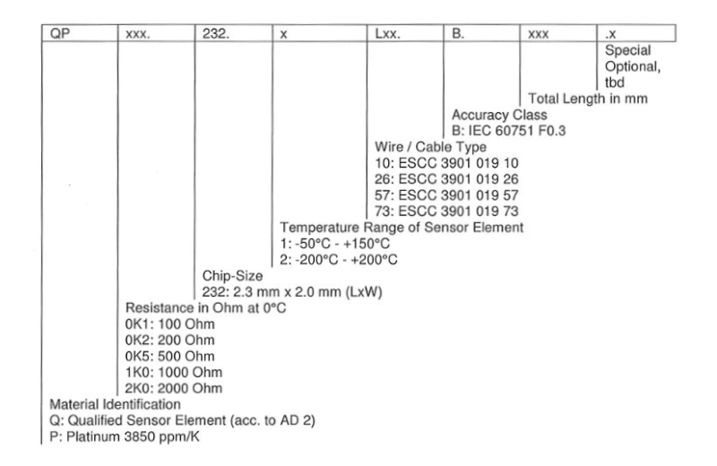
For example: QP1K0.232.2L 10.B.300
Qualified sensor element (acc. To AD 2); 1000 Ohm resistance at 0℃; Temperature range of sensor element -200℃ to +200℃; Extended with ESCC 3901 019 10 wire type; Class B accuracy according to IEC 60751 F0.3; Total wire length is 300mm
Note: Type of shrink tube (see Table 2) must be specified with each order.
Each packaging shall be marked with the production lot-number (for additional information see para. 4.6.1)
Zero power resistance shall be measured at T<sub>amb</sub> = ±25℃ ±0.3℃ and 85℃ ±0.3℃. The wire resistance shall be subtracted for the 2 wire “Platinum Temperature Sensor with Tail Extension” variants. The temperature sensor accuracy shall be recorded against serial number.
The external visual inspection shall be made in accordance to AD 1.
Criteria are as follows:
Galden heat transfter fluid film is allowable on the component.
Discoloration of lead wire and insulation is allowable (due to production and testing).
The packaging is antistatic. It is designed to protect the component from damage, typically occurred during transport and storage.